How To Calibrate The Laminator Of PIR Sandwich Panel Production Line?
Publication Date: Nov 17, 2026
Learn to calibrate the laminator of a PIR sandwich panel production line: level the double belt, calibrate thickness, pressure & temperature, align speed, run test panels, verify bonding and flatness for stable PIR panel quality.
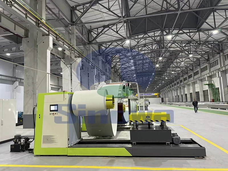
Calibrating the laminator for a PIR sandwich panel production line starts with preparing the entire equipment and production environment to eliminate external variables that may skew measurement results. Before any adjustment work begins, operators must ensure the laminator has run through a full warm-up cycle following the normal startup sequence, as uneven thermal distribution across pressing rollers and heating platens will create inconsistent bonding pressure and temperature readings during calibration. All residual adhesive buildup, hardened PIR foam scraps, and surface debris on the upper and lower pressing surfaces should be carefully cleared without scratching the polished contact areas, because raised contaminants create localized gaps that lead to uneven panel thickness and poor core adhesion after production. The feeding conveyor section connected to the laminator also needs inspection to confirm there is no side play, sagging support rollers, or misaligned guide rails that could push incoming panel materials off-center while they move into the pressing zone. Operators should lock out all automatic production controls and switch the laminator to manual jog mode, so individual components can be moved slowly and safely without triggering continuous material feeding or automatic pressure cycling. Every measurement tool used for calibration, including thickness gauges, pressure sensors, and temperature probes, should be checked for stable baseline readings to avoid relying on drifted instruments that deliver false data throughout the process. Ambient conditions around the laminator station also require attention; strong drafts from nearby ventilation fans can cool one side of the pressing assembly faster than the other, and sudden shifts in room humidity can alter how the uncured PIR foam expands before lamination. Once all surfaces are clean, the machine reaches a stable operating temperature, and measuring tools are ready, the team can move on to the initial assessment of the laminator’s pressing gap across its full working width, recording baseline values at multiple transverse points to map where deviations already exist. This baseline data acts as a reference point for every subsequent adjustment, ensuring that changes are made incrementally rather than through large, untested tweaks that risk damaging the metal facings or crushing the PIR foam core inside the sandwich panels.
The next phase of calibration focuses on the parallelism of the upper and lower pressing assemblies, a core factor that directly determines uniform panel thickness across the entire width of finished PIR sandwich panels. When the pressing platens or rollers are not perfectly parallel, one edge of the panel will be compressed more heavily than the opposite edge, resulting in tapered thickness, crushed foam core on the over-pressed side, and incomplete bonding between the PIR foam and the metal facings on the under-pressed side. Operators take repeated thickness readings at evenly spaced points from the left edge to the right edge of the laminator’s working width, placing thin, rigid test shims between the pressing surfaces at each marked position while the laminator is closed under low standby pressure. These shim measurements reveal which adjustment points need fine tuning on the lifting and leveling mechanisms that support the upper pressing frame. Adjustments to the leveling screws or hydraulic jack points must be carried out in tiny increments, with only a small amount of rotation applied at one time before rechecking the shim readings. It is critical to avoid making large adjustments on one side without matching checks on the opposite side, as this can introduce new angular misalignment even after one measurement point falls within the target range. After each adjustment, the laminator should remain closed for a short waiting period to let the heavy metal frame settle into its new position, because the weight of the upper platen can create slight delayed movement in the support structure. Operators continue recording readings at all transverse points until the gap variation across the full width stays within the acceptable tolerance range for the target panel dimension. Even minor differences in parallelism that seem insignificant during testing will become obvious defects in continuous production, as long runs of panels will accumulate thickness errors along their length and cause issues in later cutting, trimming, and assembly processes. This step cannot be rushed, and repeated cycles of adjustment and measurement are standard until the pressing surfaces maintain a consistent gap at every checked position across the working width.
Following parallelism correction, calibration work shifts to the pressure distribution system of the laminator, which controls how compressive force is applied to the PIR sandwich panel materials during the curing and bonding stage. Uneven pressure distribution prevents the PIR foam from making full contact with both upper and lower facings, creating voids, delamination spots, and weak bonding lines that reduce the overall stability of finished panels. The laminator’s pressure delivery system, whether hydraulic or pneumatic, has multiple independent force points spread across the width of the pressing frame, and each of these points must be checked individually to confirm they deliver matching force when the machine closes to the preset gap. Pressure test sensors are placed at the same transverse positions used for the parallelism checks, and the laminator is closed to the target operating gap under normal working pressure settings. Readings from each sensor are logged and compared, highlighting any zones where pressure is noticeably higher or lower than the average value across the press width. Low-pressure zones often stem from partially blocked fluid lines, worn sealing components inside cylinders, or inconsistent preload settings on individual actuators, while high-pressure zones can come from over-tensioned adjustment hardware or binding within the cylinder travel path. Operators adjust the flow regulators and preload settings for each pressure point one by one, balancing the force output so that readings stay closely grouped across the entire pressing area. After each set of adjustments, the laminator cycles open and closed several times to stabilize pressure within the lines and actuators, as trapped air inside hydraulic circuits can cause fluctuating readings that disappear after repeated cycling. Once pressure values are balanced, the team runs a short test with sacrificial PIR panel materials to observe how the foam spreads under pressure, watching for signs of uneven foam extrusion out of the panel edges that signal localized overpressure. Balanced pressure ensures that the PIR foam cures uniformly under consistent compression, forming a solid bond with facings without excessive squeezing of foam material out from the lamination zone.
Temperature calibration of the laminator’s heating system comes after pressure balancing, because the curing reaction of PIR foam relies heavily on stable and uniform heat across the pressing surfaces. Variations in surface temperature across the platens change the foam reaction rate, causing some sections of the panel to cure too quickly and become brittle while other sections cure too slowly and remain soft or poorly bonded. Contact temperature probes are laid out in a grid pattern across both upper and lower pressing surfaces, covering the central area and all edge zones where heat loss tends to be higher. The laminator is held at the target operating temperature setpoint for an extended stabilization period, and temperature readings from each probe are captured at regular intervals. Edge positions often run cooler because they have more exposed surface area losing heat to surrounding air, and internal heating channels may have reduced fluid flow toward the far ends of the platen assembly. Operators adjust the output of individual heating zones to bring the out-of-range readings closer to the target value, making gradual changes rather than large jumps in heating power, as thermal systems have slow response times and can overshoot quickly. After adjusting zone settings, the system must sit through another stabilization phase before new readings are taken, allowing heat to conduct evenly through the thick metal platen material. It is also important to check for hot spots created by internal scale buildup inside heating channels or damaged heating elements that concentrate heat in a small area. Hot spots scorch the surface of the metal facings and alter the cellular structure of the PIR foam core, creating weak spots inside the finished panel. Once all temperature readings stabilize within the desired range across the entire pressing surface, the heating setpoints are locked, and the temperature monitoring display is cross-verified against the independent probe readings to confirm the onboard control system reports values that match real surface conditions. This alignment ensures that during continuous production, the control panel’s temperature readings are reliable guides for operators running the line.
The next calibration step addresses the synchronization between the laminator and the upstream feeding system, which delivers the combined metal facings and freshly dispensed PIR foam into the pressing gap at a controlled speed. Even a perfectly calibrated laminator will produce defective panels if the feed speed does not match the laminator’s pressing speed and dwell time settings, because misalignment in timing can stretch the facings, shift the foam layer, or pull uncured material before adequate curing takes place. Operators feed a test assembly of facings and dummy foam material into the line and track the travel speed from the dispensing station all the way through the entry point of the laminator. Markers are placed on the test material at fixed intervals, and the time it takes for each marker to pass reference points on the feeding conveyor and inside the laminator is recorded to calculate actual travel speed. If the feeding conveyor runs faster than the laminator’s exit speed, material piles up at the press entrance and creates folded facings and displaced foam; if the feed speed is slower, the facings become stretched and the foam layer is pulled thin, breaking the uniform core structure. The speed controllers for the feed drive and laminator drive are adjusted to match one another, and encoder feedback signals are checked to confirm that speed commands translate into consistent physical movement. Dwell time inside the pressing zone is also calibrated at this stage, which is the duration the panel stays trapped under pressure and heat before exiting the laminator. Dwell time must match the curing requirement of the PIR formulation being used, so operators adjust the laminator travel speed to hold the material inside the heated pressing zone for the correct length of time. Multiple test runs are completed after each speed adjustment, checking the position of the foam layer relative to the facings and confirming no shifting or stretching occurs. When synchronization is correct, the composite material enters the laminator smoothly without buckling, maintains its internal layer alignment throughout pressing, and exits the press once the PIR foam has developed enough structural strength to hold its shape after leaving the heated zone.
Calibration of the laminator’s edge guide and side restraint system follows speed synchronization, as these components keep the composite panel centered while it travels through the pressing area and prevent lateral drift that causes uneven edge trim and off-center foam cores. Misaligned guides can push the facings sideways, squeezing foam toward one edge and leaving a thin, incomplete core along the opposite edge of the finished panel. Operators start by checking the straightness of the guide rails running along both sides of the laminator inlet and outlet, confirming that the guides run parallel to the center travel line of the conveyor and pressing assembly. The clearance between the guide rollers and the edge of the metal facings is adjusted carefully; too tight clearance scrapes and deforms the facings, while too much clearance allows the panel to drift sideways inside the press. Guide rollers that are worn, stiff, or binding are adjusted or repositioned so they rotate freely and apply only gentle centering force rather than rigid clamping pressure. A test panel assembly is run through the laminator while operators watch its path from entry through exit, marking any point where the panel drifts left or right and adjusting the corresponding guide position. Side restraint pressure, where adjustable hold-down rollers are used at the inlet, is also tuned to keep the top facing flat without denting the metal surface or disturbing the wet foam layer underneath. After adjustment, several test runs are performed, and the finished test pieces are measured to check the centering of the PIR foam core relative to the two metal facings. Consistent centering across multiple test samples confirms that the guide calibration is complete. Properly set guides reduce edge waste during later trimming operations and ensure that every finished panel has uniform core width and balanced edge structure, which simplifies stacking, packaging, and installation once the panels leave the production line. This step is often overlooked, yet lateral drift defects can persist even after pressure, temperature, and parallelism settings are all correct.
Once mechanical, thermal, and guide settings are adjusted, the laminator’s safety and limit switch systems require calibration to ensure all automatic stop functions trigger at the correct positions during normal operation and emergency situations. Limit switches control the maximum opening and closing travel of the upper pressing frame, preventing hard mechanical contact between the upper and lower platens when no material is present, and stopping movement if the gap closes beyond the minimum safe dimension for the target panel thickness. Operators manually jog the upper frame through its full travel range, recording the position where each limit switch activates and adjusting the switch mounting position if the trigger point occurs too early or too late. Over-travel limits must engage before the pressing frame can hit hard stops, while working gap limits should stop the closing motion at the preset target thickness so the machine does not over-compress the panel materials. The emergency stop sensors and material jam detection sensors at the laminator inlet and outlet are also tested by simulating a blockage with a rigid test piece, confirming that the drive system cuts power immediately and halts feeding when an obstruction is detected. These safety sensors can drift out of calibration over time due to vibration from continuous production, which may cause them to trigger false stoppages or fail to react to real jams. After adjusting each switch, the system is reset and tested repeatedly to verify reliable and consistent response. It is important to remember that safety calibration is not just for equipment protection; a jam inside the laminator with uncured PIR foam can harden quickly and lock the pressing surfaces together, requiring extensive cleaning and downtime to repair. Validating all limit and safety functions ensures that the calibrated operating settings can be used in routine production without unexpected equipment damage or unplanned shutdown events caused by misaligned safety hardware.
After all individual subsystems are adjusted, a series of continuous trial runs are carried out to validate the combined performance of the calibrated laminator using actual PIR sandwich panel materials matching the specifications planned for production. These trial runs are longer than the short test pieces used during individual adjustments, allowing the laminator to behave as it would under steady-state production conditions, where heat buildup, hydraulic temperature changes, and minor frame expansion can introduce small shifts in settings that do not appear during brief manual tests. Operators collect finished panels from the middle and end of each trial run, measuring thickness at multiple width and length positions, checking core uniformity, and inspecting bonding between foam and facings for any delamination or voids. The edge profile of each test panel is examined to check for consistent foam extrusion and clean facing alignment, while surface inspection looks for scorch marks, indentations, or ripples linked to leftover hot spots or pressure inconsistencies. Readings from the laminator’s onboard control system are logged continuously during these runs, tracking pressure, temperature, travel speed, and gap values to see whether they hold steady or drift gradually as the machine operates. If defects appear in specific sections of the trial panels, operators cross-reference the defect location with the earlier calibration measurement map to identify which subsystem needs a second round of fine adjustment. Small corrections are made one at a time to avoid overlapping changes that make it impossible to tell which adjustment fixed or created a problem. Several sequential trial runs are completed until panels produced at the start, middle, and end of each run show consistent quality with no recurring defects. This integrated validation stage reveals interaction effects between different laminator systems that isolated single-point checks cannot capture, confirming that calibration works as a whole rather than as a set of separate correct settings.
When trial runs produce stable, consistent panel quality, operators proceed to document all final calibration parameters and establish routine check procedures to preserve the laminator’s calibrated state over time. Every final setting value is recorded, including parallelism measurement points, pressure readings at each actuator zone, heating zone temperature offsets, feed and laminator speed ratios, dwell time, guide positions, and limit switch trigger positions. These records create a reference baseline that can be used for future recalibration after component replacement, heavy maintenance, or noticeable quality drift in production panels. The documentation also notes environmental conditions at the time of successful calibration, such as ambient temperature and general line load, because these background factors can influence how the laminator behaves. Operators mark all adjusted hardware points clearly so future maintenance staff can locate the same adjustment positions without redoing the entire mapping process from scratch. A regular inspection schedule is defined for quick verification checks between full calibration cycles; these shorter checks involve spot thickness measurements, pressure spot checks, and temperature verification rather than a complete teardown and reset of all systems. Vibration during daily production slowly loosens adjustment hardware, seals wear out, heating channels accumulate residue, and guide rollers wear down, all of which gradually shift calibration away from the validated baseline. Recording the baseline makes it easy to identify small deviations early and perform minor touch-up adjustments before defects appear in large batches of finished panels. This documentation step turns a one-time calibration task into an ongoing quality control practice, extending the usable window of accurate laminator performance and reducing the frequency of full, time-consuming recalibration procedures.
The final part of the calibration process covers post-calibration handover and continuous monitoring practices that help maintain stable laminator performance throughout PIR sandwich panel manufacturing. Once documentation is complete and trial runs pass inspection, the laminator is handed back to production operators with clear guidance on what quality signals indicate a need for rechecking calibration settings. Operators learn to watch for early warning signs such as gradual thickness drift across panel width, sudden changes in foam extrusion at panel edges, new delamination complaints, uneven surface discoloration on facings, or unexplained increases in jams at the laminator inlet. Any of these signs can signal that one calibrated parameter has drifted, and the baseline records allow maintenance teams to target the correct subsystem quickly instead of resetting the entire machine blindly. Operators are also reminded not to make arbitrary adjustments to pressure, temperature, or gap settings without referencing the documented calibration baseline, as casual tweaks can undo careful balancing across multiple interconnected systems. During normal production, spot samples continue to be pulled at set intervals for thickness and visual inspection, and any deviation from the expected range triggers a focused check of the corresponding laminator function. Over time, the team builds familiarity with how the laminator responds to normal wear and seasonal shifts in workshop conditions, making calibration touch-ups faster and more precise. A well-maintained calibrated laminator delivers consistent PIR sandwich panel quality, reduces material waste from rejected panels, minimizes unplanned downtime, and creates stable operating conditions that protect the service life of pressing rollers, heating platens, hydraulic components, and drive assemblies. Calibration is therefore not a one-time corrective task, but a foundational part of reliable line operation, ensuring that the mechanical, thermal, and motion systems of the laminator work in harmony to form uniform, well-bonded PIR sandwich panels for every production batch.
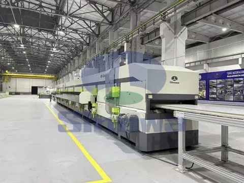
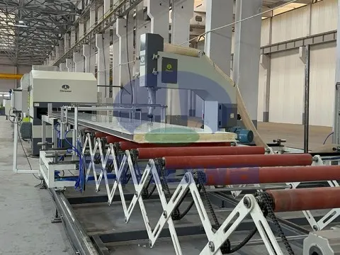
Gallery of PIR Sandwich Panel Production Line
Tags: pir sandwich panel production line, pir sandwich panel production line manufacturer, pir sandwich panel production line supplier, china pir sandwich panel production line, pir sandwich panel production line for sale
-
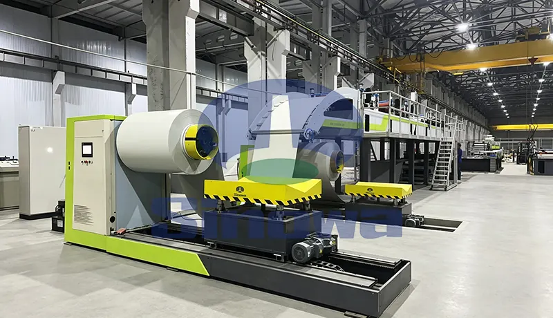
A reliable PU sandwich panel production line serves as the core equipment for manufacturing high-performance building insulation panels. This professional PU sandwich panel line features automated feeding, foaming and molding processes to ensure consistent panel thickness and structural stability. The well-designed polyurethane sandwich panel production line effectively improves production efficiency while reducing material waste in daily operation. Each calibrated polyurethane sandwich panel line can adapt to different panel sizes to meet diverse construction needs. With precise temperature and pressure control, the advanced continuous PU sandwich panel line produces panels with excellent thermal insulation and weather resistance. Meanwhile, the optimized PIR sandwich panel production line upgrades the foaming formula to enhance fire resistance performance. The high-efficiency PIR sandwich panel line maintains stable operation during long-term mass production, delivering durable and high-quality sandwich panels for various architectural and industrial applications.
-
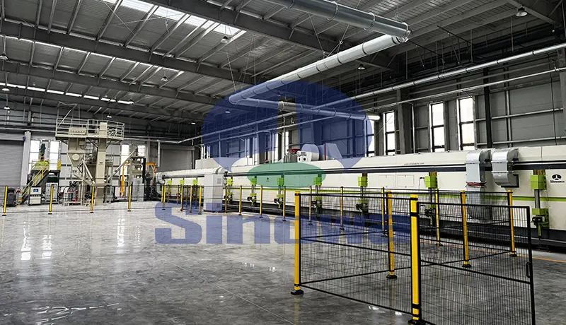
The phenolic panel production line realizes automated and continuous manufacturing of high-performance thermal insulation panels through streamlined and coordinated processing procedures.
-
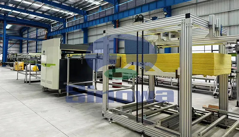
Modern insulation panel manufacturing relies on professional automated equipment to ensure stable product quality and high production efficiency. The rock wool sandwich panel production line features precise material lamination and forming processes to produce rigid, heat-insulating building panels. Meanwhile, the mineral wool sandwich panel production line adopts optimized assembly procedures to fabricate lightweight, soundproof panels widely used in architectural enclosure and thermal preservation projects.