How To Calibrate The Thickness Control System Of The PU Sandwich Panel Production Line?
Publication Date: Oct 26, 2026
Learn how to calibrate the thickness control system on a PU sandwich panel production line. Follow sensor zeroing, closed-loop tuning, hysteresis compensation and stability tests for consistent panel thickness and stable continuous foaming production.
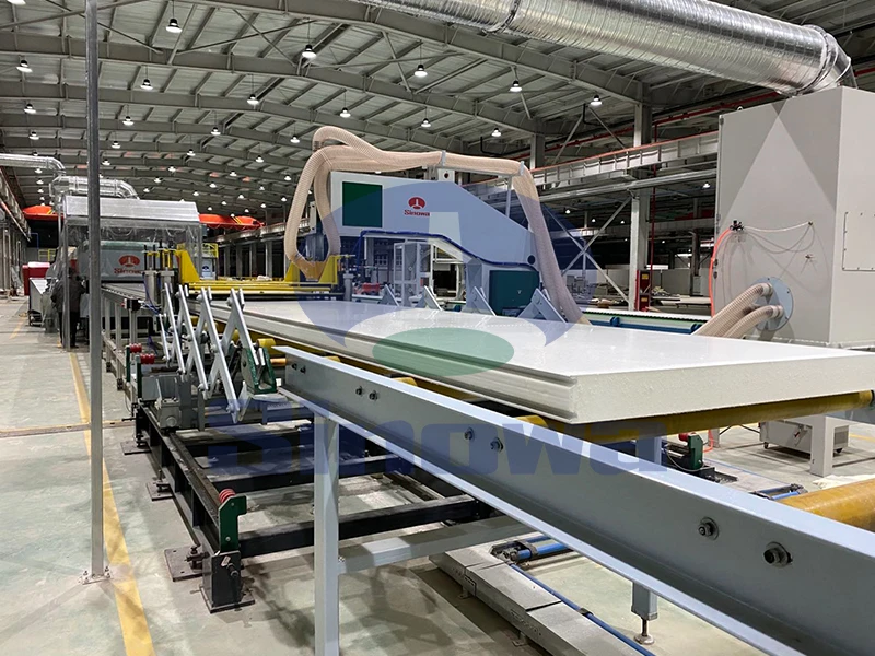
The thickness control system serves as one of the core functional modules within a PU sandwich panel production line, and its stable operation directly shapes the consistency of finished panel dimensions during continuous manufacturing. Before starting any formal calibration work, operators must first carry out a comprehensive inspection of all mechanical and electrical components connected to the control system to rule out basic faults that may interfere with calibration accuracy. It is necessary to check the flatness of the upper and lower forming rollers, confirm whether there is residual PU material adhering to the roller surfaces, and verify the flexibility of the adjusting screw structures that drive roller displacement. Loose fasteners, deformed roller surfaces, or hardened foam residue can create fixed measurement deviations, and these physical defects need to be cleaned and repaired completely before adjusting any control parameters. Operators should also inspect the signal transmission lines between thickness detection sensors and the main control unit, checking for damaged insulation, loose plug connections, or signal interference caused by adjacent high-power equipment. Any unstable signal transmission will lead to delayed or distorted feedback data, making subsequent calibration results unreliable. During this preparatory phase, the production line should be kept in a static running state without injecting PU raw materials, so that all moving parts can run freely under no-load conditions. The purpose of this no-load inspection is to observe whether the roller lifting and lowering actions respond smoothly to control instructions, without jitter, hysteresis or asynchronous movement on both sides of the roller frame. Recording the basic response characteristics of the execution mechanism at this stage helps technicians distinguish mechanical inherent errors from adjustable control errors in later calibration processes, and avoids unnecessary parameter modification aimed at problems that cannot be solved by software setting alone. This preliminary preparation work lays a solid foundation for the whole calibration process, reducing repeated adjustment cycles and helping the control system reach a stable working state more efficiently.
After finishing the pre-calibration inspection of mechanical structures and signal circuits, the next stage focuses on the zero-point calibration of the thickness detection sensors installed on the production line. Zero-point calibration establishes the baseline reference value for all subsequent thickness measurement, and any deviation in this step will cause a uniform offset in all measured data collected during formal production. Operators need to place a flat, clean reference block between the upper and lower detection probes of each sensor, ensuring that the reference block fits closely against the probe contact surfaces without tilting or gaps. The reference block used for this work should have a uniform surface and stable physical properties, so that its own thickness will not change due to slight temperature fluctuations in the workshop environment. Once the reference block is properly positioned, the control interface is operated to trigger the zero acquisition procedure, allowing the system to record the current distance signal between the probes as the zero benchmark. After storing the zero-point data, technicians should remove the reference block and check whether the sensor returns to the preset idle signal value. This verification step needs to be repeated multiple times for each sensor distributed along the production line, especially the detection units arranged near the inlet and outlet sections of the forming area, where vibration during equipment operation is relatively obvious. It is also important to pay attention to the ambient temperature around the sensors while performing zero setting. Heat radiated from the PU foaming reaction can gradually change the internal electrical characteristics of sensing elements, so zero calibration should not be carried out immediately after a long period of continuous production. Waiting for the detection area to cool down to the conventional working temperature range can effectively reduce thermal drift of the sensor signals. Stable zero-point settings ensure that the control system can judge the actual gap between forming rollers objectively, which is the prerequisite for accurate automatic adjustment of panel thickness during continuous foaming and curing.
With the sensor zero points successfully confirmed, technicians proceed to calibrate the linkage relationship between the detection signal and the roller adjustment actuator of the thickness control system. The core logic of this linkage is that when the sensor detects a deviation between the real-time panel thickness and the target value, the control unit sends output instructions to the driving components to raise or lower the upper forming roller, correcting the forming gap accordingly. At this stage, the production line is operated at a low running speed, and solid test sheets with known thickness values are passed slowly through the detection station to test the response of the whole closed-loop control loop. As the test sheet passes under each sensor, the system reads the thickness signal and automatically issues adjustment commands, and operators observe whether the roller frame acts synchronously following the signal change. If the roller movement is too slow, the control response gain needs to be increased moderately; if the roller shakes back and forth repeatedly around the target position, the gain value is too high and must be reduced to suppress oscillation. Adjusting the response parameters requires gradual fine-tuning rather than large one-time changes, because excessive gain modification can easily trigger unstable cyclic adjustment, which will cause the finished panel thickness to fluctuate periodically. While tuning the response parameters, technicians also check the synchronization of the left and right sides of the roller support frame. Asynchronous lifting on both sides will lead to inclined forming gaps, resulting in panels with uneven thickness from one edge to the other. The independent adjustment channels for the two sides of the roller frame need to be calibrated separately to guarantee consistent displacement output when receiving the same control signal. After each group of parameter adjustments, multiple test sheets are run through the line to verify the correction effect, and the parameters are locked only when the actuator can reach the target gap steadily without obvious lag or overshoot. This linkage calibration balances the response speed and running stability of the thickness control loop, preventing the system from failing to correct deviations in time or overcorrecting and creating new dimensional errors.
Once the closed-loop linkage parameters are initially tuned, the calibration process moves to trial production with PU raw materials, which distinguishes real working calibration from simple no-load testing. Unlike rigid test sheets, the foaming PU material expands continuously inside the forming cavity after mixing, and the expansion pressure exerts a continuous upward force on the upper forming roller. This foaming pressure can push the roller slightly upward and change the actual forming gap, an effect that cannot be simulated in no-load test conditions. During the trial production phase, the raw material feeding ratio and line running speed are set to conventional working parameters, and small sections of continuous panels are produced for sampling inspection. Technicians take samples at fixed intervals along the panel length, measure the actual thickness of each sample at multiple positions including the middle and two side edges, and compare the measured results with the target thickness value set in the control system. If all samples show thickness values consistently higher than the target, the system’s target gap benchmark needs to be reduced appropriately to offset the expansion force of the foaming material. If the thickness alternates between being too thick and too thin along the panel length, it indicates that the control system cannot adapt to the slight fluctuation of PU foaming pressure, and the filtering parameters for the feedback signal need to be optimized. Signal filtering helps filter out instantaneous, sharp signal spikes caused by temporary uneven material flow, preventing the system from making frequent, unnecessary adjustments triggered by transient interference. It is important to avoid setting the filter intensity too high, because excessive filtering will slow down the system’s response to real, sustained thickness deviations. Throughout the trial production calibration, operators keep records of the corresponding relationship between foaming pressure, line speed, feeding volume and final panel thickness, which helps establish adaptive adjustment characteristics for the control system under normal production conditions. This step brings the calibration result closer to the true working environment, accounting for the unique mechanical characteristics of PU foaming that affect the final forming dimension.
After collecting thickness data from trial-produced panels, technicians carry out compensation calibration for the inherent hysteresis of the thickness control system. Hysteresis refers to the phenomenon where the adjustment action of the forming roller takes a certain amount of time to affect the panel thickness at the detection position, because the foamed PU material needs a period of time to travel from the roller forming area to the sensor detection position. If the control system makes correction decisions based on the thickness signal detected at this moment and adjusts the forming gap immediately, the adjustment will actually act on the material section that enters the forming cavity after the current detected section, creating a time mismatch between detection and correction. To compensate for this hysteresis effect, the system needs to calculate the material transmission distance between the forming roller station and the thickness sensor station, combined with the running speed of the production line, to set a proper delay compensation value. When the line runs faster, the material passes through the distance between forming and detection more quickly, so the compensation time should be shortened correspondingly; when the line speed is reduced, the compensation time needs to be extended. During calibration, multiple groups of tests under different running speeds are conducted to find the appropriate compensation range. After inputting the compensation parameter, the system will store the thickness deviation signal and trigger the gap adjustment only when the corresponding material section reaches the forming area. Accurate hysteresis compensation eliminates the out-of-sync problem between detection and adjustment, and prevents the system from continuously correcting based on outdated measurement information. Without this compensation, the thickness curve of finished panels often presents a periodic offset, where corrections always lag behind the actual deviation position. This calibration item targets the time characteristic of continuous production, and it is indispensable for maintaining stable thickness along the whole length of long PU sandwich panels during uninterrupted operation.
Following hysteresis compensation setting, attention turns to the calibration of the limit protection functions integrated into the thickness control system. The limit mechanism prevents the forming rollers from moving beyond the safe displacement range, which may cause collision between mechanical parts, excessive compression of PU foam, or irreversible damage to the roller driving structure. There are two types of limit settings to calibrate: the soft limit set inside the control program and the hard limit triggered by physical travel switches installed on the roller frame guide rail. The soft limit works as the first layer of protection, restricting the upper and lower displacement boundaries of the roller through control parameters. When the control instruction is about to drive the roller beyond the preset soft limit position, the system automatically stops the adjustment action and sends an alarm prompt on the operation interface. The hard limit serves as the secondary safety barrier; if the soft limit fails to take effect, the mechanical travel switch cuts off the power output of the driving actuator immediately. During calibration, operators manually send adjustment commands to drive the roller toward the upper and lower boundary positions separately to verify whether the soft limit responds at the preset gap size. After confirming the soft limit trigger point, the hard limit position is checked to ensure that it will activate before the roller touches the fixed mechanical stopper. The distance between the soft limit trigger position and the hard limit trigger position should be reserved reasonably, leaving enough buffer space for the control system to stop smoothly. At the same time, the alarm signal output function is tested, confirming that visual and audible alarms can be activated normally when the limit condition is reached, and alarm information can be displayed clearly on the operation screen. Reasonably calibrated limit functions not only protect the mechanical structure of the production line but also avoid batch defective panels caused by the forming gap being adjusted to an unreasonable size. Even if other control parameters are set perfectly, missing or misaligned limit calibration may lead to sudden equipment failure and production interruption during long-time continuous running.
When the main control parameters, sensor benchmarks and safety limits are all adjusted, the calibration work enters the stability verification phase under extended continuous running conditions. Short trial production can only reflect the system state in a short time, while long-running verification exposes slow-changing interference factors such as gradual temperature rise of the driving motor, slow accumulation of PU foam dust on sensor probes, and slight thermal expansion of the roller support frame. During this verification process, the production line runs continuously for an extended period with stable raw material supply and constant running speed. Sampling is arranged at regular time intervals, and thickness measurement data are recorded continuously to observe whether the deviation range remains stable over time. If the thickness deviation gradually increases as running time accumulates, technicians check whether thermal expansion of the mechanical support structure has changed the basic forming gap, and add corresponding temperature drift compensation parameters into the control system when necessary. The surface condition of the sensor probes is also checked periodically during the verification process, because tiny PU foam particles can adhere to the probe surface and change the measured distance signal slowly. The control system can be configured with a timed prompt for probe cleaning, and the compensation parameter accounts for the slow signal drift caused by minor contamination that inevitably occurs in the foaming workshop environment. The operation interface is monitored constantly to observe the fluctuation range of real-time thickness signals and the frequency of automatic adjustment actions. Frequent small-amplitude adjustments indicate that the system is sensitive enough to maintain dimensional stability, while a complete lack of adjustment actions when obvious thickness deviation appears means the control dead zone setting may be too large. The dead zone parameter defines the threshold of thickness deviation that triggers an adjustment command; setting a proper dead zone avoids meaningless adjustments for tiny deviations within an acceptable range. This long-duration verification ensures that the calibration result can sustain its effect in real prolonged production rather than only performing well for a short time after parameter adjustment.
After completing continuous running verification, the calibration procedure includes cross-checking of data consistency between different thickness detection points distributed along the production line. Most PU sandwich panel lines arrange multiple thickness sensors at different positions, some near the forming outlet and others close to the cutting station, so that thickness information can be collected at multiple stages of foaming curing. Due to different environmental conditions and mechanical vibration levels at each installation position, sensors that have been calibrated separately may output inconsistent readings when measuring the same panel section. Cross-checking requires taking a single finished panel sample and moving it sequentially to the detection area of each sensor, recording the thickness reading given by each unit for the same measurement point on the panel. If fixed reading differences exist between sensors, individual offset compensation values are set for each sensor channel to unify their measurement benchmarks. This unification is critical because the main control logic may adopt signals from multiple sensors jointly to judge the overall thickness state of the panel. If one sensor consistently reads higher while another reads lower for the same position, the control unit will receive conflicting feedback signals and make confusing adjustment decisions. During cross calibration, technicians also check the transmission delay of each signal channel, ensuring that thickness data from different sensors arrive at the main controller with matching timing. After adjusting the offset compensation for each sensor, the same panel sample is tested again repeatedly until the reading difference between all detection points falls within the expected range. This step eliminates measurement inconsistency brought by the distributed layout of detection hardware, and makes the whole thickness control system operate based on a unified measurement standard. Only when all detection nodes can reflect the true panel thickness consistently can the closed-loop adjustment strategy formulated by the main controller be accurate and reliable for the full width and length of the sandwich panel product.
Once all parameter tuning, stability testing and sensor cross calibration are finished, operators proceed to store and lock the calibrated configuration data in the thickness control system. Before locking, a final round of comprehensive functional inspection is carried out to review every calibration item completed in the previous stages. The inspection covers sensor zero-point data, closed-loop response gain, hysteresis compensation time, soft and hard limit positions, signal filtering strength, dead zone threshold and individual sensor offset values. Every parameter is checked against the recorded data collected during calibration to prevent accidental modification of any setting before saving. When saving the configuration, the system stores the complete parameter set as an independent working profile, which can be loaded quickly when the production line switches back to the same product specification later. It is advisable to create a clear record of the calibrated parameter profile, noting the corresponding production conditions such as line speed range and raw material characteristic state under which these settings were validated. After data storage, the parameter modification permission is locked for ordinary operation accounts, to prevent frontline operators from changing core control parameters accidentally during routine production. Locking the configuration does not mean the thickness control system no longer needs attention; it only marks the end of a formal calibration cycle for the current product specification. When the production condition changes significantly, such as switching to a different panel thickness target or adjusting the formulation of PU raw materials, the whole calibration process needs to be performed again to match the new working condition. This storage and locking step solidifies the calibration achievements, standardizes the working state of the thickness control system, and reduces random parameter changes that would undermine the stability of panel thickness during daily manufacturing.
The final part of the calibration work focuses on establishing a regular maintenance and re-calibration schedule for the thickness control system to sustain long-term performance. Even with perfectly locked parameters, the performance of mechanical parts and electronic sensing components will degrade slowly under the continuous influence of workshop vibration, foaming heat, chemical vapour and dust. Regular inspection items include checking the wear condition of roller guide rails, verifying the tightness of fasteners on the sensor bracket, testing the sensitivity of travel switches for limit protection, and cleaning the sensing surfaces of detection probes. The frequency of re-calibration can be determined according to the daily operating hours of the production line and the stability of finished panel thickness data collected from quality checks. If thickness deviation of products begins to increase gradually or the system sends frequent abnormal adjustment alarms, targeted partial calibration should be arranged immediately instead of waiting for the fixed cycle. Technicians responsible for calibration should keep accumulating experience about how different environmental and material factors affect thickness control, so that future calibration can be completed more efficiently. It is also important to train routine operators to recognize early signs of control system drift, such as slow response of roller adjustment or abnormal thickness alarm prompts, so that abnormal situations can be reported before large quantities of defective panels are produced. Calibration is not a one-time task that is completed and forgotten; it is a recurring technical activity that maintains the dimensional consistency of PU sandwich panels. A well-maintained and regularly calibrated thickness control system reduces unstable forming conditions, improves the uniformity of finished panels, and supports the continuous and stable operation of the entire PU sandwich panel production line over a long service cycle. The value of systematic calibration lies in continuously bridging the gap between the theoretical control target and the complex, variable reality of continuous foaming forming, keeping the thickness control loop working reliably in the ever-changing workshop production environment.
Gallery of PU Sandwich Panel Production Line
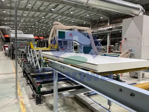
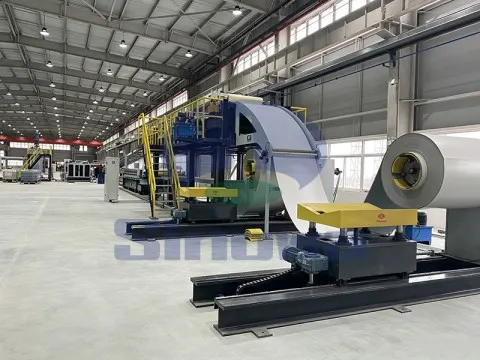
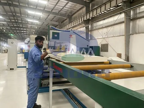
Tags: pu sandwich panel production line, pu sandwich panel production line manufacturer, pu sandwich panel production line supplier, china pu sandwich panel production line, pu sandwich panel production line for sale
-
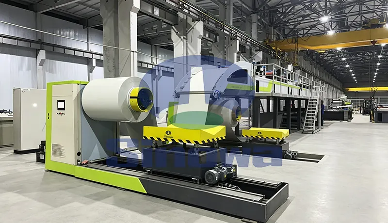
A reliable PU sandwich panel production line serves as the core equipment for manufacturing high-performance building insulation panels. This professional PU sandwich panel line features automated feeding, foaming and molding processes to ensure consistent panel thickness and structural stability. The well-designed polyurethane sandwich panel production line effectively improves production efficiency while reducing material waste in daily operation. Each calibrated polyurethane sandwich panel line can adapt to different panel sizes to meet diverse construction needs. With precise temperature and pressure control, the advanced continuous PU sandwich panel line produces panels with excellent thermal insulation and weather resistance. Meanwhile, the optimized PIR sandwich panel production line upgrades the foaming formula to enhance fire resistance performance. The high-efficiency PIR sandwich panel line maintains stable operation during long-term mass production, delivering durable and high-quality sandwich panels for various architectural and industrial applications.
-
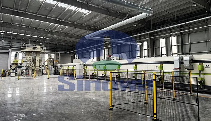
The phenolic panel production line realizes automated and continuous manufacturing of high-performance thermal insulation panels through streamlined and coordinated processing procedures.
-
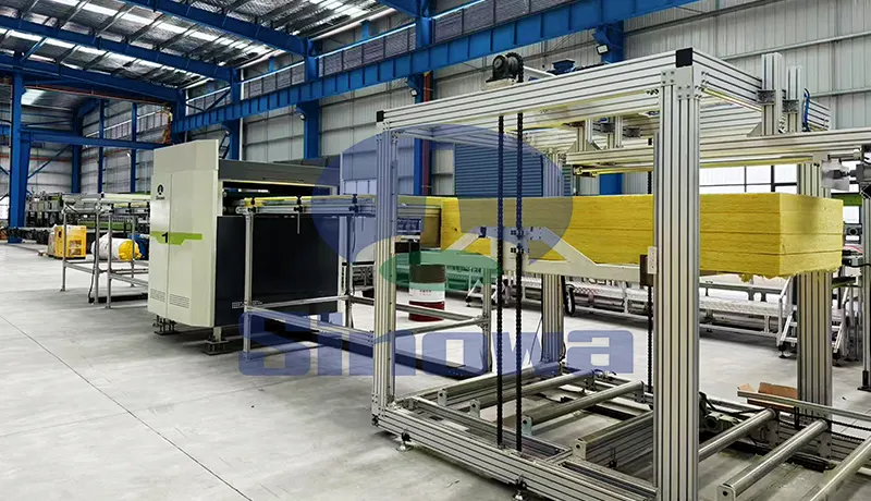
Modern insulation panel manufacturing relies on professional automated equipment to ensure stable product quality and high production efficiency. The rock wool sandwich panel production line features precise material lamination and forming processes to produce rigid, heat-insulating building panels. Meanwhile, the mineral wool sandwich panel production line adopts optimized assembly procedures to fabricate lightweight, soundproof panels widely used in architectural enclosure and thermal preservation projects.